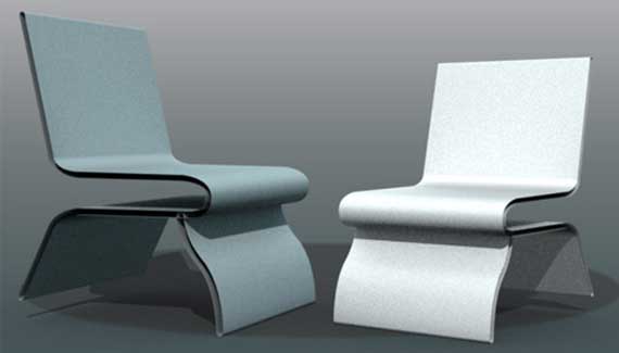
Use the Photoshop CS6 new Vector Shape Stroke feature to create a futuristic furniture design; inspired by the original Omega model located here at the3dstudio.com.
Step One: New Document Preset
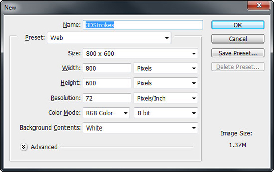
With Photoshop CS6 open, go to the File > New menu command and choose a preset preference of your choice. For the sake of this tutorial I opted for preset properties of 800×600, 72ppi with White Background Contents, as captured below. Essentially, ensure you basically have enough room in your document for moving the 3D element(s) around.
Step Two: Enable View Preferences
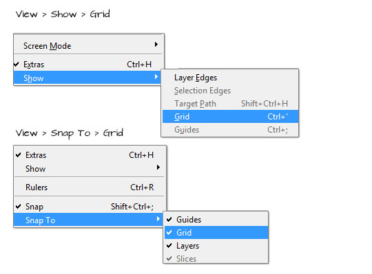
The on-start of this tutorial will create path segments and for users not acquainted with the Pen Tool (P) it is a good starting practice to have both View > Show Grid and View > Snap to Grid options enabled. These options enabled will provide accurate visual guides during the creation of the path anchor points.
Step Three: Configure Shape (Stroke) Options
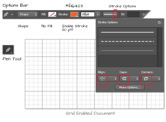
Before actually drawing the Shape Path we need to configure a few Options Bar properties.
Select the Pen Tool (P) from the Toolbar:
– Enable Shape Tool Mode;
– Set the Fill to none;
– Set the Stroke Color to an orange variant (#f16423) or a color of your choice, then alter the default stroke width from 3 pt to 10 pt;
– Click the Stroke Options and from the small drop panel, towards the bottom set Align to Center; Caps Rounded; and Corners: Rounded
Step Four: Create Single Path Outline
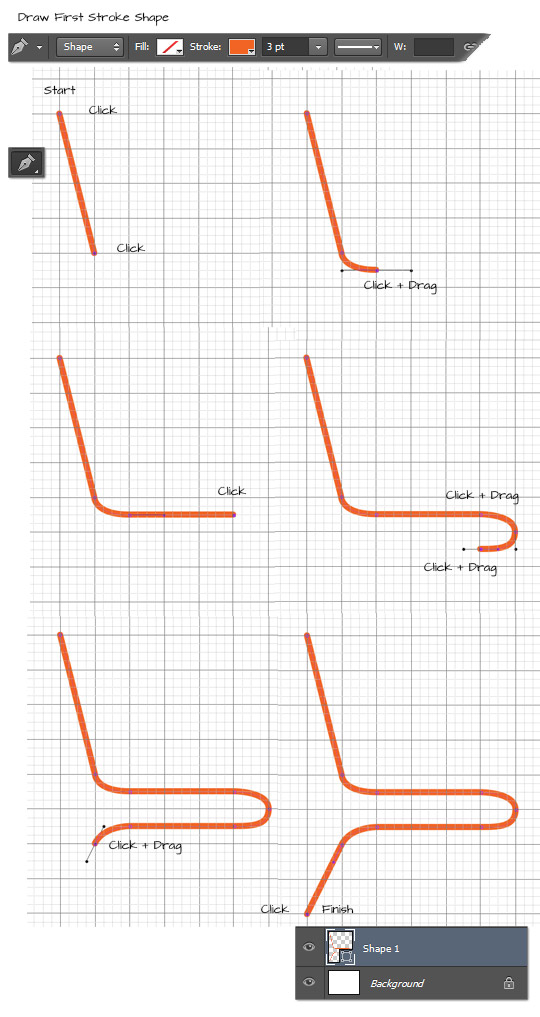
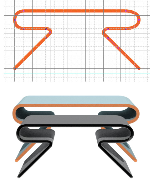
Now that the Pen Tool options are in place, let's begin the path creation. Using the caption guide below â˜start' with (a succession of) single clicks to create â˜straight' path segment; click and drag motions to create curved path segments and continue (as captured) to â˜finish' with a simple open path shape (Shape 1).
Step Five: Add additional Path Segment as Separate Layer
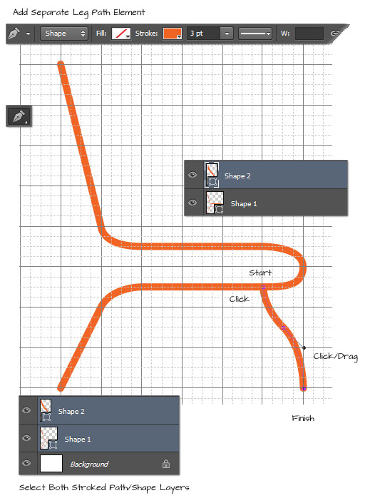
Unfortunately it's not possible to â˜combine' open path segments on a single Shape layer without losing the uniqueness of the vector Stroke, so an alternative is to create a separate stroke segment (for the leg of the chair). Use the same Options Bar settings as above then use the Pen Tool to create the leg of the chair (Shape2) as I have captured below.
Step Six: Convert Each Shape to 3D
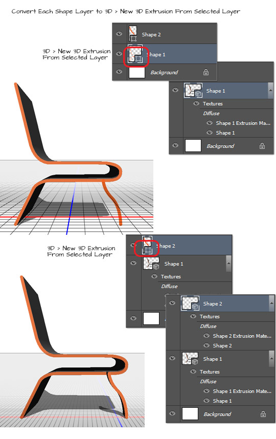
With the simple Stroke path segments in place let's convert each Shape Layer into a 3D object.
Select â˜Shape 1' Layer in the Layers Panel and go to the â˜3D > New 3D Extrusion from Selected Layer' menu command. As captured below, the top â˜Shape 1' will now be converted from a vector shape to a 3D Layer.
Select the second shape segment (Shape 2) and then go to the â˜3D > New 3D Extrusion from Selected Layer' menu command. As captured below, the bottom â˜Shape 2' is also converted from a vector shape Layer into a 3D Layer.
Step Seven: Merge Down 3D Layer
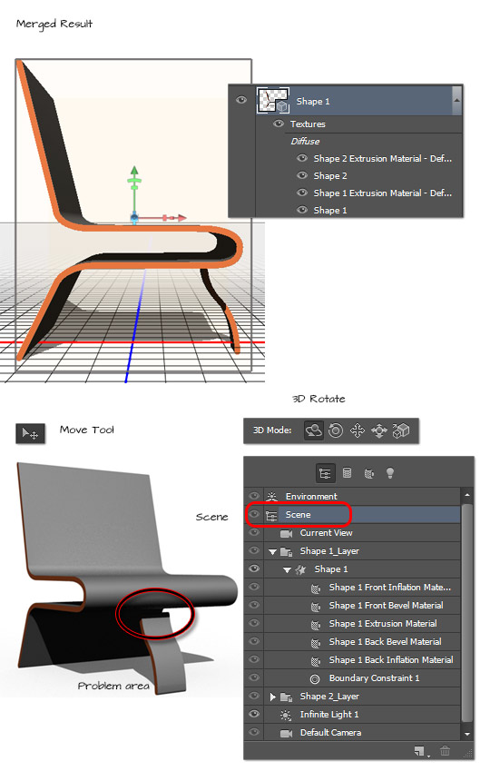
The drawback with this method is that we have two separate 3D layers not in the same environment. To correct this, select the topmost 3D Layer (in our case Shape 2) in the Layers Panel and from the panel properties context command list choose â˜Merge Down' (Ctrl/Command + E).
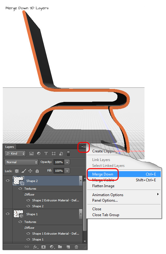
The result: 3d â˜Shape 2' is merged into the environment of 3d â˜Shape 1', as captured below, top.
Activate the â˜Move Tool'; then activate the â˜Scene' tab from the 3D Panel and adjust position of the 3D object as desired. I used the 3D Rotate Tool to â˜swing' the chair around but it still leaves an undesirable, disjointed, result. Shape 2 (the separate leg segment) does not match the extrusion of the base nor is it â˜connected' to the base of the chair.
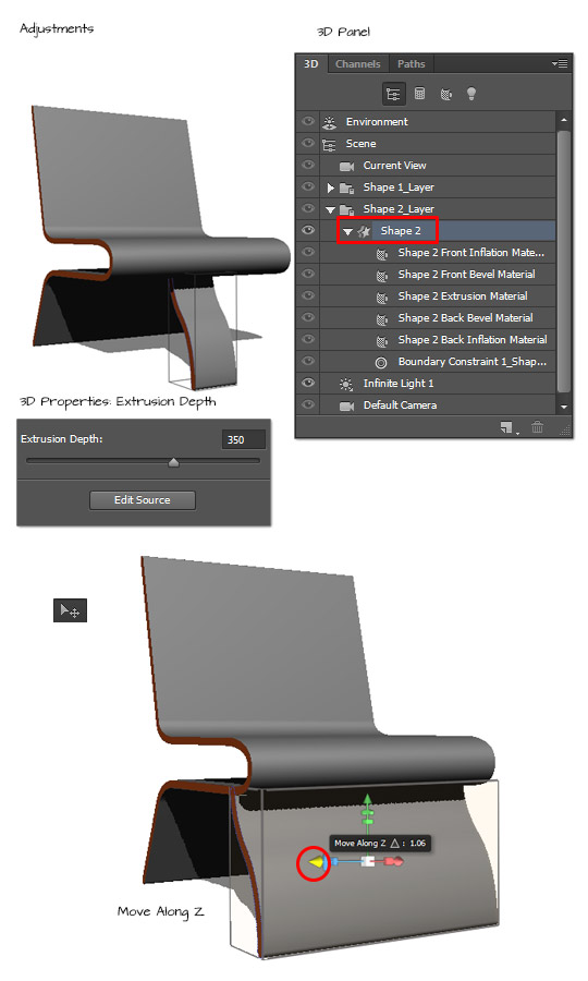
To correct the Extrusion shortfall, go to the â˜3D Panel ☠and select Shape 2 (as encased in red, below) then in the Properties Panel adjust the Extrusion Depth to match that of the chair base. In my case it is a setting in in the 350 range.
Then activate the Move Tool and hover over the yellow 3D transform visual arrow and drag leftward to â˜Move along the Z' until it is in place with the base of the chair.
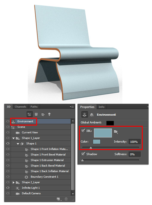
There are plenty of texture and color properties that can be applied; one quick alteration that is new to Photoshop CS6 is the simplified Environment > Image Based Light (IBL) property, as captured below. As a quick color alteration select the 3D Panel > Environment tab and from the Properties panel adjust the IBL (Image Based Light) color option. As captured below I opted for a light blue color. Explore other color variations and go to the 3D > Render menu command to raytrace the final result.
Here are some alternatives –
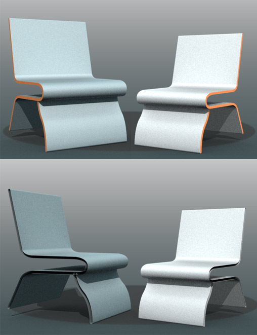
Create table stroke path using the same above (step 4) process and convert to 3D layer (Step 5).
Until next week
Happy trails

awesome trick…thanks
Your welcome, Kartik
Have fun.
Wey that really mad dread good job!!!!!!!!!
i have done it at home very interesting and thank you so much for sharing your knowledge with us i request you for more guide regarding graphic designing because i want to learn it more and more thanks dear bye
awesome feature of CS6, Great job